Notifications

7 minutes, 3 seconds
-23 Views 0 Comments 0 Likes 0 Reviews
We are a top-tier control valve manufacturer in China, delivering superior valves and control actuators designed to meet the diverse needs of various industries.
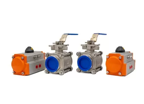
Pneumatic actuators are crucial mechanical devices used in a variety of industrial applications to automate the operation of valves, dampers, and other control systems. They convert compressed air into linear or rotary motion, providing reliable and efficient performance in process control.
Proper installation is vital for ensuring optimal performance, longevity, and safety. This guide outlines a step-by-step process for installing pneumatic actuators, covering preparation, mounting, connection, testing, and troubleshooting.
Before diving into the installation process, it’s important to understand the different types of pneumatic actuators and their uses:
Quarter-Turn Actuators: Used for ball, butterfly, and plug valves, they provide 90-degree rotational motion.
Linear Actuators: Employed in gate and globe valves, these actuators convert air pressure into straight-line motion.
Rack-and-Pinion Actuators: Use a gear mechanism to produce rotary motion.
Scotch-Yoke Actuators: Ideal for high-torque applications, commonly used in larger industrial valves.
This guide focuses on quarter-turn pneumatic actuators, the most commonly used type in industrial settings.
Gather Necessary Tools and Materials
Make sure you have the following tools:
Wrenches (adjustable, socket, or spanner)
Screwdrivers (flathead and Phillips)
Thread sealant (Teflon tape or liquid thread sealant)
Torque wrench
Alignment tools (if needed)
Safety gear (gloves, goggles, protective clothing)
Verify Compatibility
Ensure the actuator is suitable for the valve, checking factors like torque, size, and mounting pattern. Confirm that the valve’s shaft type (square, round, keyed, or splined) is compatible with the actuator.
Safety Precautions
Depressurize the system and lock out the compressed air supply.
Isolate the valve, ensuring it’s not under pressure or handling hazardous fluids during installation.
Always follow the manufacturer’s instructions for both the actuator and valve.
Inspect Components
Actuator: Look for any shipping damage (e.g., dents, cracks, or bent shafts).
Valve: Ensure the valve’s sealing surfaces are clean and undamaged.
Mounting Hardware: Check that bolts, washers, and couplings are in good condition.
Mounting the Actuator
Align the Actuator with the Valve: Position the actuator over the valve, ensuring the mounting holes line up correctly, especially for ISO-standard actuators.
Secure the Actuator: Insert bolts and washers, tightening them evenly in a criss-cross pattern. Use a torque wrench to apply the manufacturer-recommended torque to prevent damage from over-tightening.
Connecting the Shaft
Keyed Shafts: Slide the actuator onto the valve shaft, ensuring the keyway is properly seated.
Spline Shafts: Align the splines before securing the actuator.
Set-Screw or Clamp Couplings: Tighten the set-screws or clamping mechanism to prevent slippage.
Pneumatic Air Supply Connections
Identify Air Ports: Most actuators have two ports—one for extending (opening) and one for retracting (closing). Double-acting actuators require air to both ports, while single-acting actuators use a spring return.
Connect Air Lines: Use the appropriate fittings (NPT, BSP, or metric threads) and apply thread sealant to prevent air leaks. Avoid over-tightening.
Install FRL Unit (if applicable): A filter, regulator, and lubricator unit ensures clean, dry, and properly pressurized air.
Electrical Wiring (for Smart Actuators)
If the actuator includes position sensors or solenoid valves, follow the manufacturer’s wiring diagram, ensure proper grounding, and test the signal communication with the control system.
Initial System Check
Perform a visual inspection to ensure all bolts, fittings, and connections are secure.
Test the manual override (if available) to check smooth operation.
Power-On and Functional Testing
Gradually Introduce Air Pressure: Slowly increase pressure to avoid sudden movements.
Observe Actuator Movement: Ensure smooth operation without jerking.
Cycle Testing: Open and close the valve several times to ensure consistent operation. Check for air leaks at connections.
Position Verification: Ensure the valve reaches both the full open and closed positions. Adjust limit switches (if equipped) to fine-tune travel stops.
Performance Adjustments
Speed Control: Install flow control valves if needed to adjust actuator speed.
Torque Adjustment: If applicable, adjust spring preload to achieve optimal torque.
| Issue | Possible Cause | Solution |
|---|---|---|
| Actuator not moving | No air supply, blocked ports | Check air lines, clear obstructions |
| Slow operation | Low air pressure, restricted flow | Adjust regulator, check for leaks |
| Air leaks | Loose fittings, damaged seals | Tighten connections, replace seals |
| Valve not fully closing | Misaligned shaft, incorrect limit setting | Realign shaft, adjust limit switches |
| Excessive vibration | Unbalanced load, high speed | Install dampers, adjust flow control |
To ensure long-term performance:
Lubrication: Follow the manufacturer’s guidelines for greasing moving parts.
Leak Checks: Periodically inspect air lines and fittings for wear.
Calibration: Recheck limit switches and sensors annually.
Proper installation of pneumatic actuators is essential for efficient valve operation and system reliability. By following this guide, you can ensure a smooth installation process, optimize performance, and reduce maintenance issues. Always refer to the manufacturer’s documentation for specific instructions and consult engineering specialists for complex systems.
Tip: Keep a record of the installation process, including torque settings and adjustments, for future maintenance.Know more about Google SEO Directory

