Notifications

4 minutes, 2 seconds
-28 Views 0 Comments 0 Likes 0 Reviews
Pneumatic control valves play a vital role in numerous industrial applications, offering precise control over fluid and gas flow by converting air pressure into mechanical motion. These China Control Valves are commonly used in processes where automation and efficient flow management are critical. Understanding how these valves work, the common faults they may encounter, and effective troubleshooting techniques is essential for maintaining operational efficiency and minimizing downtime.
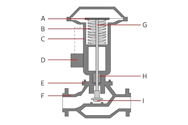
The Anatomy of a Pneumatic Control Valve A pneumatic control valve consists of several key components, each serving a distinct purpose in ensuring smooth and accurate flow control:
Actuator (A) The actuator transforms air pressure into mechanical motion. Types include:
Diaphragm Actuators: Flexible diaphragm used in low-pressure applications with quick responses.
Piston Actuators: Suitable for high-pressure environments, using a piston for motion.
Single-Acting Actuators: Air pressure moves in one direction; a spring returns it.
Double-Acting Actuators: Air pressure moves in both directions, enhancing control.
Spring (B) Used in single-acting actuators, the spring ensures the valve returns to a safe position if air pressure is lost.
Yoke (C) A structural component connecting the actuator to the valve body, maintaining alignment and reducing vibrations.
Positioner (D) Ensures precise valve positioning based on control signals. Types include:
Pneumatic Positioners
Electro-Pneumatic Positioners
Digital Positioners
Bonnet (E) A pressure-tight housing covering the valve stem, allowing access for maintenance.
Valve Body (F) The main valve structure housing components like the valve seat and plug. Types include:
Globe Valves: Precise throttling control
Ball Valves: Quick operation, minimal pressure drop
Butterfly Valves: High flow, low pressure
Gate Valves: On/off control
Valve Stem (G) Connects actuator to internal components, transferring motion to open or close the valve.
Seals and Gaskets (H) Prevent air or fluid leakage, maintaining efficiency and safety.
Valve Seat and Plug (I) Regulate flow by allowing or obstructing it. Material choice and precision are key for sealing and durability.
Common Pneumatic Control Valve Faults
Air Leaks: Due to worn seals or cracked hoses, weakening actuator performance.
Sticking or Jamming: Caused by debris or corrosion, affecting movement.
Actuator Failure: Due to wear, damage, or pressure loss.
Positioner Malfunction: Leads to incorrect valve positioning.
Seal Wear and Leakage: Degrades pressure control and safety.
Troubleshooting Techniques
Review Maintenance Records: Identify patterns or recurring issues.
Visual Inspection: Look for damage, wear, corrosion, or leaks.
Check Air Supply: Verify pressure, inspect for leaks or blockages.
Actuator Inspection: Test movement, check for leaks and proper signal.
Positioner Calibration: Ensure accurate control by checking for faults.
Control Signal Verification: Check for signal accuracy and interference.
Manual Operation Test: Ensure smooth movement, listen for odd noises.
Internal Component Inspection: Clean and replace worn parts.
Pipeline Inspection: Remove blockages or corroded sections.
Conclusion Pneumatic control valves are crucial for automated processes, providing reliable flow regulation. Regular maintenance and understanding of their function, faults, and troubleshooting steps ensure their optimal performance and extended service life.Know more about Google SEO Directory

